

Aluminum alloy is widely used in industrial products due to its excellent physical properties, and almost all welding methods can be used to weld aluminum and aluminum alloys. However, aluminum and aluminum alloys have different adaptability to various welding methods, and each welding method has its own application field.
Due to improper selection of welding methods and welding process parameters, aluminum alloy parts undergo severe deformation after welding, or defects such as weld porosity, slag inclusion, and incomplete penetration can cause cracks or material looseness in the weld metal, seriously affecting product quality and performance. The following editor will take you to analyze the methods and precautions for aluminum alloy welding.
01.Three welding methods for aluminum alloys
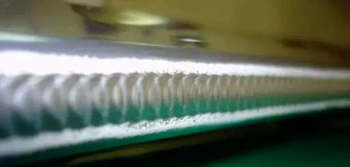
Tungsten inert gas arc welding
The tungsten inert gas arc welding method is mainly used for aluminum alloys and is a good welding method. However, the tungsten inert gas arc welding equipment is complex and not suitable for outdoor operation.
Resistance welding and seam welding
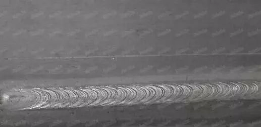
This welding method can be used to weld aluminum alloy thin plates with a thickness of less than 5mm. However, the equipment used during welding is relatively complex, with high welding current and productivity, making it particularly suitable for large-scale production of parts and components.
Pulse argon arc welding
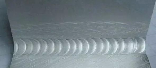
Pulse argon arc welding can greatly improve the stability during the welding process by adjusting parameters to control arc power and weld formation. The welded parts have small deformation and heat affected zone, making them particularly suitable for welding thin plates, all position welding, and welding forged aluminum, hard aluminum, superhard aluminum, etc. with strong thermal sensitivity.
02.Welding precautions for aluminum alloys
1.Before welding aluminum alloy, the surface of the aluminum alloy must be cleaned to prevent oil stains, dust, and other contaminants. Acetone can be used to clean the surface of the aluminum alloy welding area. For thick plate aluminum alloy, a steel wire brush should be used to clean it, and then acetone should be added for cleaning.
2.When welding aluminum alloy, the surface of the aluminum alloy should be cleaned first, without oil fumes, dust, etc. In addition, thick plate aluminum alloy should be cleaned with a steel wire brush, and then cleaned with acetone.
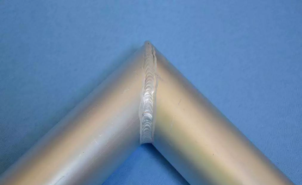
3.If the plates can be preheated after comparison, it can prevent insufficient preheating from causing incomplete welding. When extinguishing the arc, a small current should be used to fill the pit.
4.When welding, it is necessary to standardize and weld according to the thickness of the plate.
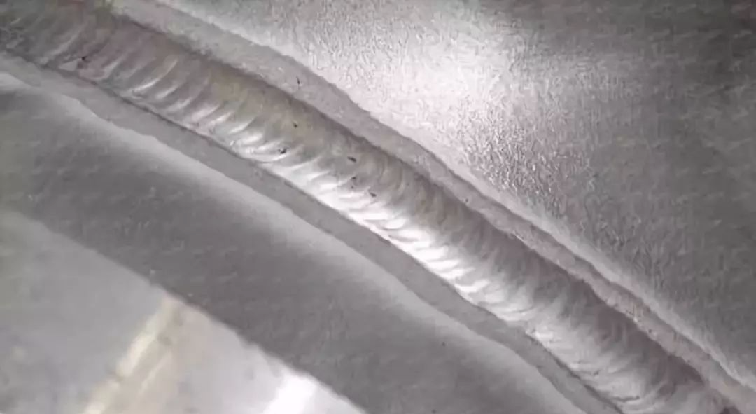
5.The cable of the welding gun should not be too long, as it can cause stable wire feeding.
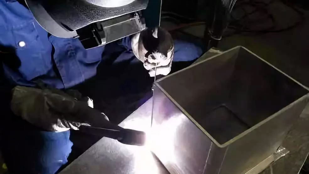
03.Welding material requirements
01.Selection of protective gas
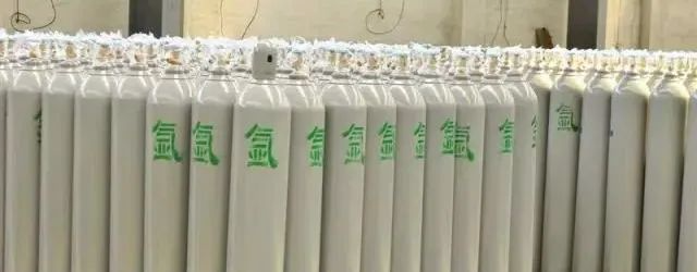
The shielding gases used during welding include inert gases argon (Ar) and helium (He), which are commonly used in production. The argon gas used for welding aluminum and aluminum alloys must meet the following purity (volume fraction) requirements: gas greater than 99.99%, ammonia less than 0.04%, oxygen less than 0.03%, and water mass fraction less than 0.07%. At present, the purity of domestically produced gas generally meets this requirement, so there is no need for further purification treatment before use.
02.Selection of tungsten electrodes
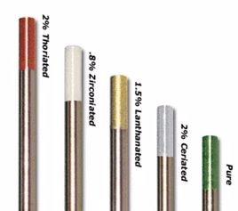
There are four types of tungsten electrode materials used in argon arc welding: pure tungsten, thorium tungsten, cerium tungsten, and zirconium tungsten. Pure tungsten electrodes have high melting and boiling points, making them less prone to melting and volatilization. However, their electron emission ability is inferior to that of thorium tungsten and cerium tungsten. Adding a thorium oxide (Tho) electrode with a mass fraction of 1.0%~2.0% to pure tungsten is called a thorium tungsten electrode. It has strong electron emission ability, high allowable current density, and stable arc combustion. However, thorium has a certain level of radioactivity, which poses obstacles to its promotion and application. The commonly used cerium tungsten electrode (grade WCe20) is made by adding a mass fraction of 1.8%~2.2% cerium oxide (impurity ≤ 0.1%) to pure tungsten. Cerium tungsten electrode has low electron escape work, high chemical stability, high reliability of repeated arc ignition, high allowable current density (such as when using DC positive argon arc welding, the allowable current density is 5%~8% higher than that of thorium tungsten electrode), low burn loss rate, and eliminates radioactivity.
03.Selection of solvents
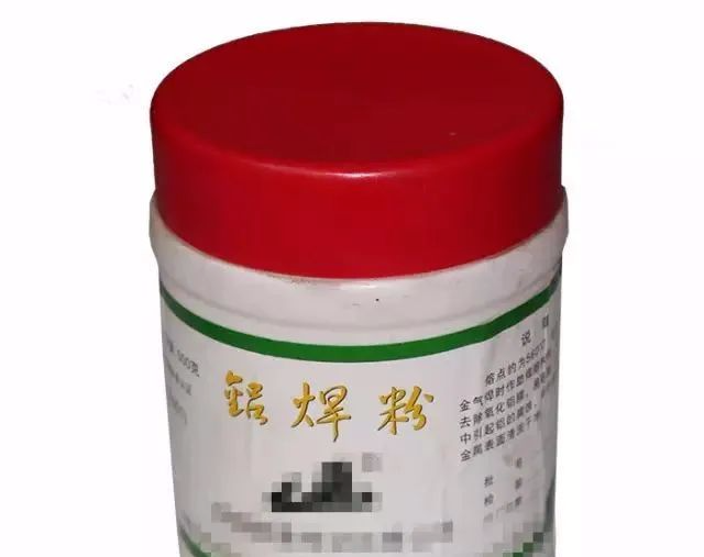
During gas welding and carbon arc welding, the melted metal surface is prone to oxidation and forms an oxide film. To ensure welding quality, it is necessary to remove the oxide film and other impurities with flux. The flux used in gas welding and carbon arc welding is a mixture of chloride and fluoride powders of various elements such as potassium, sodium, lithium, and calcium. When using gas welding, carbon arc welding, corner welding, lap welding and other methods to weld joints, the residual slag on the welded part is often difficult to completely remove. In this case, different fluxes should be selected according to different aluminum alloy materials. For aluminum magnesium alloys, it is not advisable to use fluxes containing sodium.
04.Selection of tungsten wire
In the welding process of aluminum alloy materials, the selection of welding wires for aluminum alloy is crucial. Before selection, the following content should be understood:
·Can all aluminum alloy materials be used as welding filler alloys?
·Can all aluminum alloys be welded?
·What are the defects that should be avoided?
·How to choose welding filler alloys?
·What are the criteria to consider when making a choice?
Aluminum alloy series requires understanding
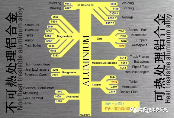
What kind of welding wire should I choose?
A single base material can be welded using multiple aluminum alloy welding materials, such as welding 5083-5083: welding wires such as 535651835556 can be used. However, the welding joint obtained from each type of welding wire may only be optimal in one performance aspect. When selecting the best welding wire, the main consideration should be the final performance of the welded component. Overall, the following performance indicators are mainly examined:
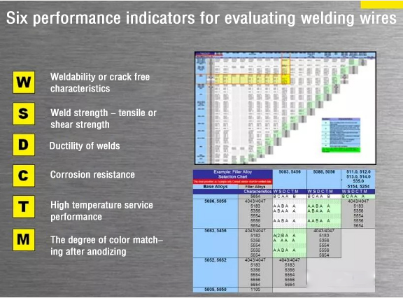
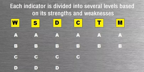
In summary, in the process of selecting aluminum alloy welding wires, the most suitable alloy filler can only be selected after a thorough analysis of many relevant variables in aluminum welding and its application. The first thing to consider is the type and chemical properties of the base material, followed by the performance requirements of the welded components. Finally, when developing and evaluating suitable welding process parameters, the selection of alloy fillers is an indispensable part.
05.Welding Welder:
Passed the examination in accordance with Appendix A of the Aluminum Container Welder Examination Rules.
06.Preparation before welding
1. Mechanical methods (including cutting) should be used for aluminum groove processing. If plasma flame method is used for processing, no less than 3mm of the discolored part should be removed by mechanical processing. The surface of the processed groove should be flat and smooth, without cracks, layering, inclusions, burrs, burrs, and oxidation colors. The surface of the groove should have a silver white metallic luster: if necessary, 100% PT should be applied to the groove and within a range of no less than 50mm on both sides.
2.Surface cleaning (including removal of surface oxide film, scales, contamination, and unqualified oxide color) must be carried out on the welding wire, groove surface, and within a range of no less than 50mm on both sides. Polishing can be done using a 0.15-0.2 stainless steel wire disc brush, metal grinding head (i.e. electric milling cutter), manual disc milling machine, file (should be an aluminum specific curved file), scraper, and acetone (the white cloth dipped in acetone should be clean, do not use cotton cloth or cotton yarn to avoid fuzzing during wiping). However, it should be noted that these tools should be cleaned before use, and attention should also be paid not to press the oxide film into the base material during cleaning, so do not use too much force during cleaning; But it is not allowed to use grinding wheels or ordinary sandpaper to polish, because aluminum is very soft and causes sand particles to stay in the aluminum, which can easily produce defects such as pores and slag inclusion after welding.
3.For outsourced hot processed components, such as heads, 100% PT should be applied to the surface of the aluminum material after entering the factory, and if necessary, RT should be applied to areas that cannot be determined.
4.The surface of the welding wire can be cleaned with a stainless steel wire brush or clean sandpaper; For welding wires with thick surface oxide skin, chemical cleaning is required after polishing before welding. Chemical cleaning: Soak in a 70 ℃, 5% -10% NaOH solution for about 0.5-3 minutes, rinse with clean water, then soak in a 15% HNO3 solution at room temperature for about 1-2 minutes, rinse with warm water, then dry with a handheld hair dryer (not an air compressor, as there is water and oil in the air), and dry in an oven at 100 ℃ before use. This method can also be used for aluminum materials.
5.Clean welding wires and components should be kept clean and dry, and the welding area should not be touched or blown by hand. Welders generally wear white welding gloves and should not wear dirty gloves for fear of trouble; Pollution is strictly prohibited before welding, otherwise it should be cleaned again. Local pollution can be cleaned again: it is best to cover both sides of the groove with white paper. After general mechanical cleaning, welding should be carried out immediately. If welding is not carried out within 4 hours after cleaning, it should be cleaned again before welding.
6.The assembly of welded parts should be accurate. If the assembly is poor, it is necessary to consider replacing the components instead of forcibly assembling them to avoid excessive stress. Before formal welding, the groove size should be checked and qualified before construction.
7.The welding wire used for positioning welding and the process measures taken are the same as the welding process.
8.When assembling welded parts, avoid positioning welding at stress concentration points (such as weld intersections and corners on the workpiece) as much as possible. The length and spacing of positioning welding seams can be shown in the following table: (mm)

9.The welding seam should not have defects such as cracks, pores, or slag inclusions, otherwise it must be removed and re welded. Re welding should be carried out in nearby areas, rather than spot welding in place; When the process does not specify, the gap between butt welds can be 2-4mm.
10.For positioning welds that will melt into permanent welds, it is necessary to ensure penetration and remove the oxide layer on their surface (only silver white is allowed), and to make the transition between the two ends of the weld smooth for arc connection. Otherwise, it should be repaired. When welding on cold parts, the arc should stay for a while at the beginning of the welding until the edge of the base metal begins to melt, and then add wire welding in a timely manner to ensure that the starting welding point is fully welded.
11.When welding longitudinal seams, it is necessary to place start and stop plates at both ends of the welded part. The start and stop plates should be made of aluminum of the same grade and thickness as the welded part. Try to avoid creating arc pits when welding circumferential seams.
12.During the welding process, if the positioning welding point cracks, causing misalignment or gap changes on the plate edge, welding should be stopped immediately and can only continue after repair.
13.During the welding process, the black ash and oxide on the surface of the upper weld seam should be cleaned with a steel wire brush first. When welding, pay attention to handling the flame, that is, at the end of the arc. The arc can be started 10-20mm away from the starting end of the welding, and then quickly return to the starting end for welding. The first layer is welded in a straight line. In order to obtain good forming, other layers can be welded in a horizontal swing and stopped on both sides for fusion.
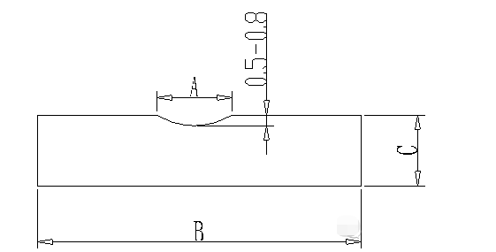
14.Aluminum welding deformation and collapse are prone to occur during welding, so targeted fixtures and pads should be made before welding. When using fixtures, both the front and back of the parts generally need to be clamped, and the rigidity and clamping force of the fixture should be moderate, because if it is too small, it cannot control deformation. If it is too large, the weld seam will be too restrained, which can easily lead to weld cracking. The clamping force should be 350Kg/100mm. Soft aluminum fixtures can be made of carbon steel or stainless steel, which can slow down heat dissipation; Aluminum fixtures can be made from aluminum to enhance heat dissipation. The longitudinal seam fixture can be keyed, while the circumferential seam fixture can be hydraulic bulging. When assembling longitudinal seams, the gap can be appropriately increased to allow for shrinkage after welding; Rings (including circular flanges, flanges, etc.) should be left with some reverse misalignment or flipping, as the flanges will collapse and deform after welding. The material of the base plate is generally stainless steel or carbon steel. For welding aluminum materials with low requirements, graphite can be used to make the base plate. When selecting the material for the backing plate, the influence on the cooling speed of the weld should also be considered. When the aluminum plate is thick or the assembly gap of the backing plate is large, the gap can be sealed with clay mud and removed after welding. The size of the cushion plate can be as shown in the following figure:

07.Welding requirements
1.Certified welders should weld according to welding process documents and other documents.
2.In case of any of the following situations in the welding environment, effective protective measures should be taken, otherwise welding is not allowed:
1)The welding environment is not clean, with dust and smoke;
2)Welding environment wind speed greater than or equal to 1.5m/s;
3)The relative humidity of the welding environment is greater than 80%;
4)Outdoor work in rainy or snowy weather;
5)Welding temperature below 5 ℃:
3. Aluminum products should be welded in a dedicated area, which should be covered with rubber or velvet cloth; When welding, it should be kept away from ventilation openings and doors and windows to avoid affecting the gas protection effect.
4. Handmade tungsten gas arc welding of aluminum materials is generally done using alternating current to produce cathode egg effect. Melting electrode argon arc welding is done using direct current reverse welding. When using DC welding due to equipment limitations, there is usually an oxide film or even black ash on the welding surface, which can be wiped off with a wire brush or cloth. The white film formed on the surface of the weld due to residual flux or oxidation can be wiped off with a wire brush or cloth dipped in hot water.
5.Preheating before welding: Due to the strong thermal conductivity of aluminum materials, when manual tungsten inert gas welding is used for thicknesses greater than 10mm, preheating should be carried out before welding, but not exceeding 100 ℃. The interlayer temperature during welding should also not exceed 100 ℃. Depending on the specific situation, use flames or far-infrared plates for heating.
6.During the welding process, the filling point of the welding wire should not be located directly below the arc, but at the edge of the molten pool, about 0.5-1.0mm away from the centerline of the arc. The filling point of the welding wire should not be higher than the surface of the molten pool or swing laterally under the arc to avoid affecting the melting of the base material, damaging gas protection, and causing metal oxidation; When retracting the welding wire, do not expose the end of the welding wire outside the gas protection zone, to prevent the end of the welding wire from being oxidized and then brought into the molten pool when it is sent back in. If the tungsten electrode touches the weld metal during welding, the welding should be stopped immediately. Use a metal grinding head to remove contamination and repair the tungsten electrode; Both before and during welding, the oxidized part at the end of the welding wire should be cut off before welding.
7.A weld seam should be welded as much as possible in one go, and when welding again after stopping midway, the overlap should be 10-20 mm. Before proceeding to the next weld seam, the surface color of the previous weld seam should be checked, and only silver white is allowed; And thoroughly remove surface pollution, slag inclusion and other defects. The arc crater should be filled and the arc connection should be fused and welded through. The general method for extinguishing the arc is to use the stack height extinguishing method: when extinguishing the arc, the arc is raised at a constant speed, and the welding wire is accelerated to be filled until the arc is extinguished, causing the weld seam at the extinguishing point to protrude locally. If necessary, excess height exceeding the standard should be polished. When there is a attenuation device on the welding machine, this arc extinguishing method has a better effect.
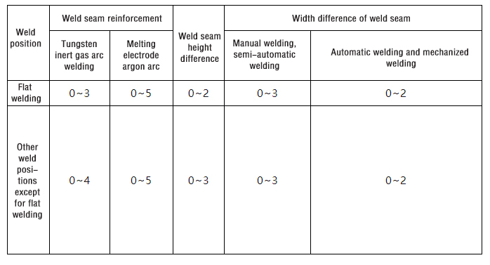
8.The reinforcement height, difference in reinforcement height, and width difference of Class A and B joint welds are shown in the following table mm:
9.When the thickness of the shell is ≤ 12mm, the D-type weld between the connecting pipe and the shell should generally be butt welded with the shell edge, with a height of 25-30mm.
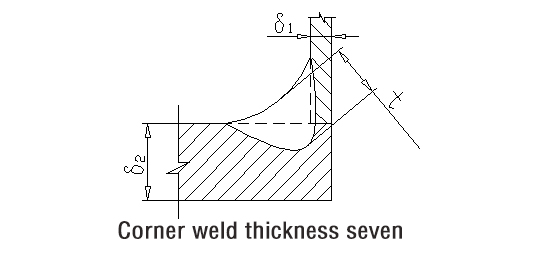
10.The thickness t of the weld seam for Class 10. C and D joints, unless otherwise specified in the drawing, should not be less than 0.7 times the smaller value of the component thickness 61 and 62 on both sides of the fillet weld, and should not be less than 3mm. In general, it should not exceed 10mm (as shown in the figure below). When using a cover plate lap fillet weld for lining or composite plate composite, the thickness of the cover plate forms one side of the fillet weld, and the length of the weld leg is generally limited by the length of the side. When L2 ≤ 4mm, T ≥ 0.7L2 should be required.
11.The weld seam of Class C and D joints should have a smooth transition with the base metal.
12.The surface of the weld and heat affected zone should be 100% inspected, and there should be no defects such as cracks, lack of fusion, pores, arc pits, slag inclusions, and splashes. There should be no arcing points outside the weld.
13.There should be no undercut on the surface of the weld seam of aluminum pressure vessels. The depth of undercut on the surface of atmospheric pressure vessel welds should not exceed 0.5mm, the continuous length of undercut should not exceed 100mm, and the total length of undercut on both sides of the weld should not exceed 10% of the length of the weld.
14.Welding sequence of heat exchanger tubes: tube plate assembly (the reserved length of heat exchange tubes should not be less than 4mm for later machining); Cleaning of pipe ends and pipe plates; Expansion tube at one end; Weld one side of the tube plate; Machined unwelded heat exchange tube ends; Expansion tube: cleaning of tube ends and tube plates; Weld the heat exchange tube without welding one side. When welding, the first layer is generally not welded with wire (whether the first layer undergoes PT or airtightness testing according to regulations), but other layers should be welded with wire.
15.Aluminum welding should pay attention to the large blunt edge of the groove, usually 2-6mm. For joints with backing plates, the blunt edge can be appropriately reduced. When the aluminum plate is thin, butt welding should consider edge pulling, for example, when ≤ 3mm, edge pulling and non wire welding should be considered. Aluminum welding can be done simultaneously on both sides, with or without wires added on the back depending on the specific situation.
08.Weld repair
1. For defects that require repair, the causes should be analyzed, improvement measures should be proposed, and welding repair processes should be developed (considering the prevention of welding deformation during processing) before starting repair (the table below shows the analysis of welding defects and their causes in general situations);
2.The number of repairs to the same part of the weld shall not exceed 2 times.
3.Generally, metal grinding heads are used to remove defects and grooves. If the defect is deep, it can be manually milled and polished using the specified method first, and then the surface of the groove can be polished with a metal grinding head. The groove should have a uniform width, a smooth surface, and a groove that is easy to weld. There should be a certain slope at both ends of the groove (generally not greater than 1:4).
4.Before repairing, the defects must be cleaned thoroughly, and a 100% PT confirmation should generally be performed (if the defect is a crack, a 100% PT must be performed). When repairing welding, simply remove all the defects and do not dig too deep. If necessary, perform RT to confirm that the defects have been completely removed. When repairing welding, do not fill the wire first and use an arc to melt the metal in the repair welding area; After filling the wire, the arc should be slightly biased towards the welding wire to prevent overheating of the metal in the repair welding area. The arc can move back and forth moderately in the direction of the repair welding length to prolong the existence time of the molten pool and facilitate the escape of hydrogen bubbles from the molten pool.
5.The performance and quality requirements of the repaired weld seam should be the same as the original weld seam;
6.The main weld defects in aluminum welding are porosity and cracks:
6.1 Causes of porosity: Aluminum welding porosity is mainly formed by hydrogen entering the welding pool. Hydrogen sources include: materials, welding wire, protective gas, wire feeding mechanism, welder's gloves, and high environmental humidity, such as contaminated welding wire, oxide film on the material and welding wire itself, oil stains or sweat stains on the wire feeding mechanism, etc. Preventive measures:
6.1.1The hydrogen content in the material and welding wire is ≤ 0.4mL/100g;
6.1.2 The surface of the welded part should be cleaned of oil stains and oxide films, and the storage time should not exceed 4 hours. After surface cleaning, cover the groove and both sides with a dry, clean, and lint free object;
6.1.3 Use polished welding wire as much as possible, otherwise the treatment method is the same as above;
6.1.4 Impurity content in protective gas: H2 ≤ 0.001%; 02 ≤ 0.02%; N2 ≤ 0.1%; H20 ≤ 0.02%;
6.1.5 Protective gas pipeline: Generally, stainless steel or copper pipes are used, and plastic hoses are used instead of hoses that are easy to absorb water such as rubber; Before welding, the cooling water pipeline should be checked to ensure that there is no water leakage; When the environmental humidity is high, the protective gas should be heated and the pipeline should be purged:
6.1.6 Wire feeding mechanism: There should be no oil stains. The wire feeding tube should be made of polytetrafluoroethylene or nylon, and the contamination and condensate inside the tube should be cleaned before welding;
6.1.7 On site environment: The temperature shall not exceed 25 ℃, the relative humidity shall not exceed 50%, and the environment shall be kept clean;
6.1.8 Welder: Work clothes should be white as much as possible, so that contamination can be detected and cleaned up in a timely manner. Pay attention to sweat and oil stains during welding to avoid contaminating the welded parts again;
6.1.9 Before welding, test welding should be carried out on the test plate to check whether the protective gas and pipeline are qualified.
6.1.10 Preventive measures for welding process: Use double-sided welding instead of single-sided welding; When each weld seam is thinner than when it is thicker, it is beneficial for gas pores to escape; Large diameter welding wire is beneficial for reducing porosity; Preheating before welding and slow cooling after welding; Reducing arc voltage, increasing current, and reducing welding speed are beneficial for reducing porosity.
6.2 Cause of crack formation: Poor material weldability; Not considering crack resistance when selecting welding wires; The structural constraints are too great. Preventive measures:
6.2.1 For aluminum materials with poor weldability, their crack resistance should be considered before welding, rather than just strength; If necessary, consider annealing and welding the welded parts, followed by quenching and aging after welding.
6.2.2 Choose welding wires with good crack resistance, such as those containing low melting point elements such as Si.
6.2.3 Minimize the restraint of welding joints as much as possible, arrange the welding sequence reasonably, and allow the weld seam to have lateral shrinkage allowance to reduce welding stress. If it is not necessary to perform positional welding, do not perform positional welding. If it is possible to perform double-sided positional welding, do not perform single-sided positional welding.
6.2.4 Try to switch from single-sided welding to double-sided welding as much as possible.
09.Testing requirements
1.After welding the joint of the head, 100% RT should be performed, and after forming, 100% RT or 100% PT should be carried out according to the regulations.
2.Class A and B welds are generally subjected to 100% RT.
3.Perform 100% PT on the C and D welding joints on the container.
4.Perform 100% PT on the surface repair welding seam of aluminum material.
5.Perform 100% PT on the weld marks of the temporary fixed connection welds of aluminum fixtures and tie bars after removal.
6.Other parts required for inspection in the drawings.