Summary:
In recent years, with the continuous updating of design concepts, the shapes and forms of architectural design have become increasingly complex and diverse. Owners often have bold ideas in pursuit of novelty and uniqueness, which puts forward higher requirements for curtain wall design, especially for the design of unit curtain walls with large angle twists.
This article conducts CAD simulation analysis on the design of large angle torsion unit curtain walls, analyzes their basic design ideas, and summarizes the issues to be paid attention to in design, providing reference for future peers in designing similar projects. Due to the fact that the stress installation method (commonly known as the cold bending method) is a conventional method with low design difficulty and is solved by forcing external forces to achieve deformation and installation of the plate, this article does not conduct research on this and only analyzes the unit curtain wall system with large torsion angles that cannot be adapted to the cold bending method.

01 Preface
At present, there is a gradual increase in the use of spatial torsion design in buildings, with novel exterior effects and complex designs. The external curtain wall can be constructed using either a frame method or a unit method. The frame curtain wall method is relatively simple and the construction difficulty is relatively low. The design difficulty of the unit curtain wall is much greater because it is sealed through insertion. As the unit panels are assembled into a whole in the factory, all possible problems should be solved or as much as possible during the design phase, There are no more than three design solutions for this project:
1. Stress installation method (also known as cold bending method);
2. Space frame method, which is the solution for large angle torsion unit curtain wall discussed in this article.
3.Flat panel construction, with panels staggered and arranged in a fish like manner. (However, this method cannot achieve smooth fitting of surfaces, which will not be discussed in this article)
02.Advantages and Disadvantages of Three Solutions
1. Stress installation method: Assemble into a flat plate, install with stress on site, and force the deformation of the plate to achieve the overall torsion effect of the exterior facade, commonly known as cold bending method.
Advantages:
a. The design is relatively simple, and according to the conventional unit curtain wall method, it is only solved through installation. 6. The price is better than the space frame method: regardless of material usage and processing costs, it is the same as the conventional unit method.
Disadvantages:
a.There is currently a lack of relevant research on the mechanical properties of brittle materials such as glass, which have been subjected to long-term torsional stress for curtain wall members and panels; Due to this installation method, the deformation of the plate is forcibly achieved through external forces, and the fourth point of the plate (referring to the point outside the plane) is forced to reach a certain point outside the plane through connection with the adapter system, thereby achieving the overall torsion effect of the outer facade. Therefore, this method is solved through installation, specifically a non design solution.
6.The scope of application is relatively small, and this method is only applicable to designs with small spatial torsion. For unit curtain walls where the vertical distance between the fourth point (referring to the point outside the plane) and the plane determined by the other three points of the plate is not large (hereinafter replaced by h), as the value of h is related to the grid width and plane torsion angle, it can be derived through geometric formulas. However, there is currently no relevant research and no corresponding theoretical results for reference, In principle, the value of h should not exceed 20mm (personal suggestion), and this method can be used. This value is for reference only and can also be determined through experiments.
c.The installation difficulty is relatively high. Due to the fact that the unit curtain wall is installed through insertion, when the target plate is in place, its adjacent plates are still flat before they are in place. It will be difficult to insert and connect with the twisted plates, and professional tools must be used to complete the installation.
2.Space frame method: The factory assembles it into a special-shaped plate, with the fourth point of the plate (referring to the point outside the plane, which is not coplanar with the other three points of the plate) to achieve the overall torsion effect of the outer facade and achieve normal installation on site. The panel material is flat like glass, but adjacent panels are staggered (if the skeleton is not considered), and it is a fish scale like cloth as shown in Figure 5 and Figure 6.
Advantages:
a.To achieve stress free insertion, the installation method is the same as that of conventional units. b. To achieve large angle torsion unit projects that cannot be achieved by cold bending. c. If designed properly, all the performance of flat units can be achieved. d. The external decoration effect is good and has no impact.
Disadvantages:
a.The fourth point (referring to the point outside the plane) is not coplanar with the plane determined by the other three points of the plate, making it difficult to process.
b.The drainage design may lead to an increase in unit transom and a slight increase in cost.
c.The design is difficult and requires higher requirements from designers.
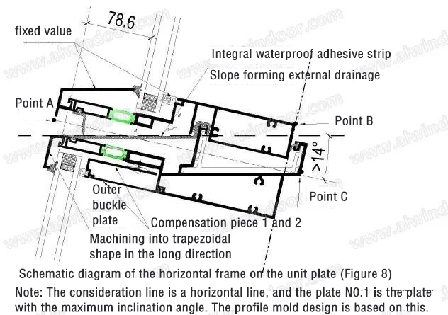
d.The indoor horizontal keel is not at the same elevation. If point A in the middle of the outer facade is used as the benchmark, there will be a phenomenon where point B or point C of the indoor horizontal frame of different sections is higher on the left, right, or left (as shown in Figure 8). If the spacing between room columns is large, it will affect the indoor effect.
e.The left and right glass are not on the same isotherm, resulting in a slight decrease in insulation performance.
3.Plate construction method:
Advantages:
a. The design is relatively simple, following the conventional unit curtain wall method, and the stress system is reasonable.
b.Simple processing and installation.
Disadvantages:
a.The panels are staggered like fish scales, which cannot achieve a smooth fitting surface and has an impact on the exterior effect.
b.The left and right vertical frames are not of equal length and the profiles are larger than the above two methods.
03.Spatial geometric characteristics of 03 large angle torsion element
The plates of the torsion unit curtain wall are generally designed as spatial parallelograms, and the fourth point (referring to the point outside the plane) of the unit curtain wall has a small vertical distance from the plane determined by the other three points of the plate (hereinafter replaced by h). As the value of h is related to the grid width, plane torsion angle, and the grid size of the plate inside the unit curtain wall, it can be derived through geometric formulas. This article takes the illustrated engineering as an example to derive the relationship between the value of h and relevant parameters, The formula is:
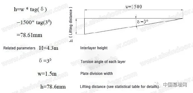
CAD 3D lofting can also be used to measure the h value. After comparison, the theoretical calculated value is completely equal to the measured value (see Table 1).
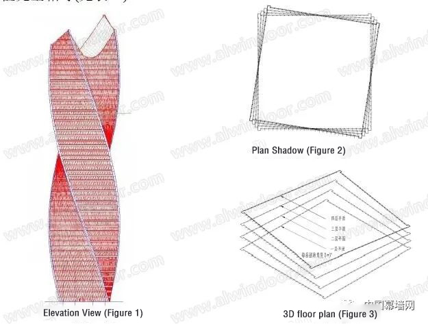
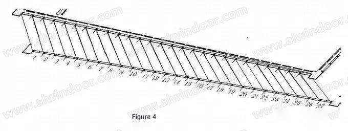
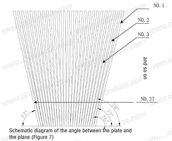
In order to determine the size and shape of the surface material, we need to first find the size between the centerline of the grid and the angle between adjacent edges. The grid size (Table 1) minus the structural thickness of the system can obtain the design size of the surface material (i.e. the cutting size during construction). Because the unit system using the spatial frame method has a flat surface material such as glass. The size of the lifting distance (h) determines whether to use the cold bending method or the spatial box method. To achieve this, a three-dimensional layout of a plate between layers is required, as shown in Figure 4, which shows the plate numbering diagram. From left to right, it shows NO.1, NO.2... NO.27.
After measuring 27 plates, a theoretical numerical statistical table of plane grid size was obtained (Table 1).
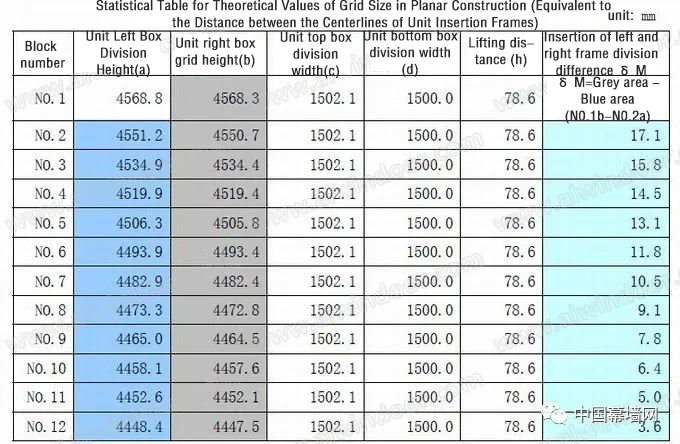
。Analyzing the above statistical data, it can be seen that the lifting distance (h) is a certain value of 78.6mm. If the cold deformation method is used, the surface material and skeleton need to achieve such a large deformation under forced external forces to achieve the building effect. Due to the brittle material of glass, the material requirements are obviously too high, and the project itself requires high cost. If the system is not selected properly, causing damage to the plate will result in expensive later maintenance costs, which is not worth the loss, In summary, the spatial frame method is adopted.
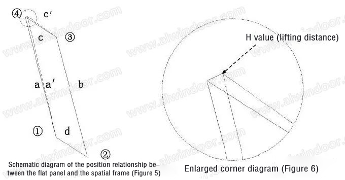
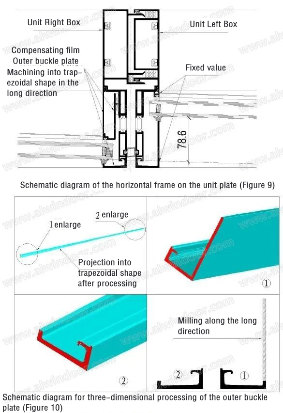
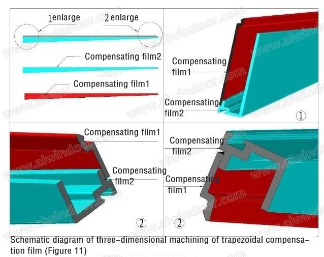
Table 1 shows that the value of a is approximately equal to the value of b, the value of c is approximately equal to the value of d, and the angle between the glasses is equal. Therefore, the surface material can be designed according to a parallelogram. The relationship between the position of the flat panel and the spatial frame is shown in Figure 5 using the fully hidden curtain wall design rule. If the design is an open frame unit curtain wall, the panel should be retracted into the profile groove, forming two triangular gaps on the edges a and c. This requires consideration of these two triangular gaps during structural design, including compensation strips; As the end of the aluminum profile should not be machined into sharp triangles, it should be designed as a trapezoid, as shown in Figure 11.
When using the exposed frame unit curtain wall design, the glass should be embedded in the groove formed by the keel and the outer buckle plate. The trapezoidal compensation strip formed by the two edges a and a, c and c is the indoor keel gap compensation strip, and the other is the outdoor trapezoidal compensation strip, which can be milled from the outdoor aluminum buckle plate. At the same time, due to the fact that the project is located in a cold area and requires a heat cutoff design, the design difficulty is greater. The following is a three-dimensional lofting analysis of the design details.
04Design characteristics of large angle torsion unit
1.Design of drainage slope parameters for torsion units
Due to the different angles between the plates and the horizontal plane, as shown in the schematic diagram of the angles between the plates and the plane, all 27 plates have different angles with the horizontal plane. The minimum angle is 760, with internal and external inclinations. As the transom is designed perpendicular to the glass plate, the external drainage slope must be greater than 760 when designing the transom on the unit to achieve smooth drainage (for the internally inclined plates of this project); The design of the most unfavorable section is shown in Figure 7.
In order to reduce the cross-sectional size of aluminum profiles, the design adopts an integral waterproof adhesive strip. The integral waterproof adhesive strip is generally 50 meters per roll, which has reliable waterproof sealing, excellent sealing effect at the cross joint position, and few bonding links. Relying on the adhesive strip, the isolation of the inlet and outlet water channels at this unit position can be achieved, and it will not be damaged in case of plate displacement. However, the amount of adhesive strip is large and the price is high. However, it can achieve excellent waterproof effect, As shown in Figure 8
2.Design of trapezoidal compensation strip
From the schematic diagram in Figure 5, it can be seen that if the spatial frame method is used, there are two adjacent edges of the glass panel that are parallel to the keel and do not require additional compensation plates, such as edges b and d, so the notch for clamping the glass is a fixed value; The other two edges need to be compensated in order to better grip and fix the flat glass and space frame, as shown in Figures 9 and 10. The three-dimensional diagram is as follows (Figure 11).
3.Design of triangular gaps on the interface between the horizontal and vertical frames of the unit after torsion
The interface between the horizontal and vertical frames of the torsion unit is non vertical, so when the various surfaces intersect, triangles will be generated between the outer profiles of the frame material, which mainly affect the performance in the following aspects:
a.Outer facade horizontal and vertical decorative buckle plate
This part is located on the exterior facade, and the triangular gap needs to be considered. Extending the vertical decorative buckle plate can effectively solve this problem. Another advantage of this approach is that it solves the installation difficulty of aligning the horizontal and vertical buckle plates. The artificial design is uneven, and the decorative effect is good.
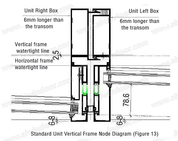
b.The design of the gap at the intersection of the horizontal and vertical keels on the indoor side. The triangular gap between the horizontal and vertical frames can be lengthened, as shown in Figure 12. As it was anticipated that the horizontal frame would extend beyond the tail of the vertical frame, layout 2. When the vertical frame was artificially lengthened by 3mm, there were still gaps of 1.81mm on the left, 1.81mm on the right, 1.93, and 2.62mm on the right, indicating that the original pre lengthened 3mm was not enough, A maximum value of 262mm can be used for further lengthening design, with the vertical frame being extended to 6mm compared to the horizontal frame. To ensure that the air tightness is not affected, sealant can be applied at the junction of the horizontal and vertical keels and the position of the adhesive strip to ensure the sealing effect and still meet the requirements.
c.Design of gaps in the insertion position.
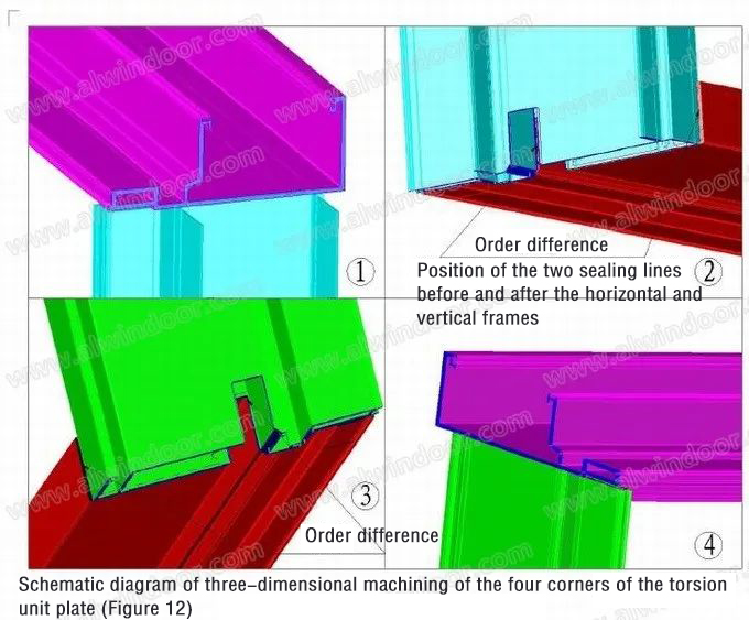
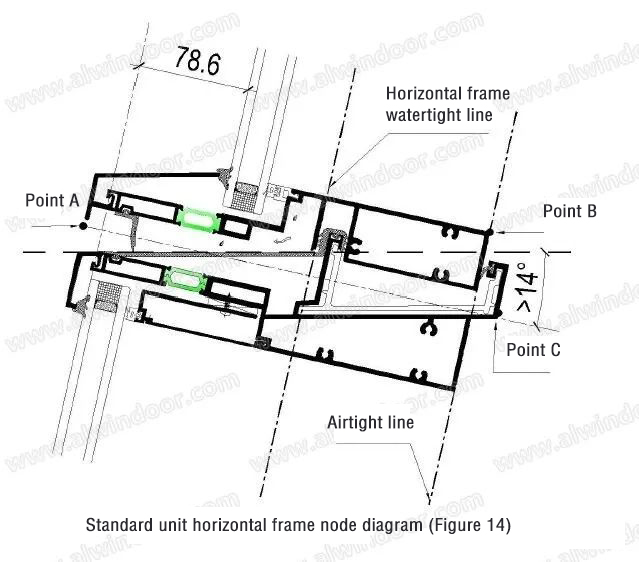
As shown in Figure 2.3 above, there is a step difference in the positions of the two sealing lines before and after the horizontal and vertical frames. In Figure 2, the sealing line of the vertical frame was artificially placed 1.8mm behind the sealing line of the horizontal frame during the lofting process. However, from the three-dimensional view, the sealing line of the horizontal frame is still 0.3mm behind. Therefore, in the formal design, the sealing line of the vertical frame can be placed 2.1mm behind the sealing line of the horizontal frame. Considering the assembly error, this value can be increased to 2.5mm, At the same time, thicken the wall thickness at the sealing line of the mullion to 5mm. When adding chains to the mullion, appropriate cutting pins can be made to ensure that the sealing line is in the same plane. In summary, the adjusted horizontal and vertical standard unit node diagram can be designed according to the diagram (Figures 13 and 14):
4.Indoor "tail shaking" phenomenon of torsion unit mullion
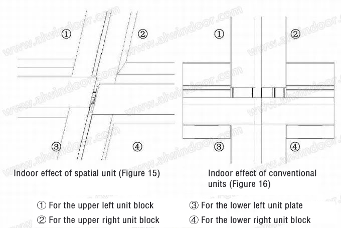
From Figure 15, it can be seen that the vertical joints of the four units are not in the same straight line, and a step difference will be formed between the upper and lower layers. This is different from the normal flat unit curtain wall, as shown in Figure 16. However, since this area is located within the interior decoration surface and separated by the floor slab, although this phenomenon may exist in practice, it will not affect the interior effect; From the orthographic projection of Figure 5, it can also be determined that this value is 4mm. The horizontal frames of the left and right panels are not at the same elevation. As mentioned in the second section above, the disadvantage of the spatial frame method is that the indoor horizontal keel is not at the same elevation. If the midpoint A of the middle panel on the outer facade is used as a benchmark, there may be a phenomenon where the B or C points of the indoor horizontal frames of different panels are higher on the left and right bottom or higher on the right and left bottom (as shown in Figure 8). If the spacing between the room columns is large, it will affect the indoor effect. However, this problem can be compensated for through the design of the interior decoration.
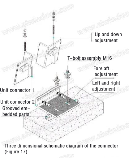
5.Design of spatial quadrilateral unit connectors
From the statistical data in Table 1, it can be seen that the value of a is approximately equal to the value of b, the value of c is approximately equal to the value of d, and the angle between the glasses is equal. Therefore, the orthogonal projection of the spatial quadrilateral element is approximately a parallelogram. To simplify the design, the connectors can be designed according to the characteristics of the parallelogram element, mainly to ensure three-dimensional adjustment.
The material of the connectors can be aluminum alloy or carbon steel. From a cost perspective, carbon steel connectors are more competitive. This article takes carbon steel connectors as an example to illustrate their design, as shown in Figure 17:
05Design considerations
Due to the use of CAD 3D simulation analysis in this article, other unforeseen issues may occur during factory processing, assembly, or installation. Therefore, management procedures can be implemented to reduce design errors in specific curtain walls and avoid losses; Samples, experiments, trial assembly, and system improvement can be conducted first, and mass production and assembly can only be carried out after maturity.
For this type of irregular design, 3D lofting is essential to identify patterns. The 27 standard layer plates mentioned in this article can also be uniformly refined according to adjacent plates (if the size difference between adjacent plates is small, within a certain range, according to one design) to reduce the types of plates.
Due to the fact that the space unit plates are not in the same plane, it is unfavorable for installation and transportation. To enhance their torsional performance, steel or aluminum angle codes can be used to strengthen the horizontal and vertical connections. Additionally, attention should be paid to reserving lifting holes on the connectors.
For different types of torsion projects, due to differences in grid width and torsion angle, the extension size of the vertical frame and the setback size between the sealing lines of the horizontal and vertical frames are not the same. Therefore, independent lofting is necessary before final confirmation. The relevant dimensions in this article are specific to this project and are not universal, but the principle of their operation is the same. This method can also be used for hidden or semi hidden frame unit curtain walls with torsion surfaces.
There is also a triangular gap problem at the intersection of the front faces of the horizontal and vertical frames at the groove of the adhesive strip. However, it can be solved through changes in the elastic deformation of the adhesive strip, or by covering the outer edge of the profile with a large adhesive strip, without affecting the sealing and appearance.
There is a certain angle between the adjacent plates above and below the unit. In this project, the angle is 1 degree, so there will be a 1 degree angle between the upper and lower transoms of the unit. Therefore, the angle is small, and the insertion parts can be designed according to the plane. During installation, this impact can be eliminated through adhesive strips and insertion gaps.
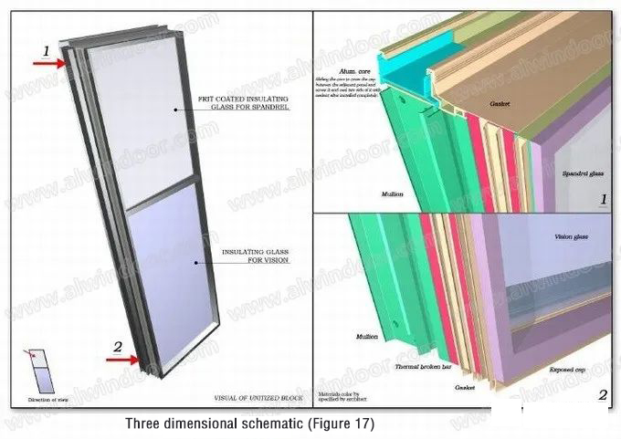
After the above analysis, the relative position between the surface material and the keel was determined, and the final rendering effect of the 3D lofting of the simulation image is shown in Figure 17:
06.Conclusion
Although there is no experience to draw on in the design of such a complex unit curtain wall, it is not because the industry has not ventured into sand that we do not try. To engage in technology, one must first understand the basic principles before designing and evaluating the system. First, determine whether the system is feasible. If the design system is judged to have problems from the 3D layout, it must be re selected first. Otherwise, the consequences will be endless. With the powerful 3D functions of CAD, by building models for analysis, simulating reality, discovering problems, and improving the system, we can quickly and economically evaluate a set of systems, This puts higher demands on the basic skills of designers. From the previous text, the use of a sliding unit system can be fully suitable for the use of torsion shaped projects. With slight improvements in details, other performance is almost unaffected.
The article is from China Curtain Wall Network, written by Du Dongxin

High quality products, high-quality services and high-quality

Focus on us
HANBERT
Tel: 0757-22682270
Phone: +86-135 314 008 83
E-mail: info@hanbert-tech.com
Address: 1612,4th,building,ZhiyePlaza,Daliang,Foshan,Guangdong P.R.of china
Copyright © 2021-2026 HANBERT All Rights Reserved. 粤ICP备2021118030号  Power by:
 Hanelink.com